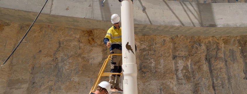
Groundwater monitoring wells are the backbone of reliable data collection across mining, civil infrastructure and environmental projects in Australia. They provide continuous data on groundwater levels and quality, track contamination spread and support engineering decisions that carry real consequence. When bore construction is poor or well design ignores site conditions, the result is misleading groundwater quality and level data, increased risk of cross contamination between aquifers and potential non-compliance with approval conditions.

In Western Australia, all water bores must adhere to the Minimum Construction Requirements for Water Bores in Australia (MCR), published by the National Uniform Drillers Licensing Committee. Monitoring wells often require stricter specifications than supply bores because the purpose is measurement, not extraction. This article covers practical engineering design choices: location, depth, screened interval selection, correct materials, gravel pack, annular seals, well development and instrumentation.

Monitel is an engineering-led groundwater monitoring partner that designs and instruments groundwater monitoring wells and bores for long-term, automated data collection. For project-specific support, Monitel’s dedicated wells and bores service outlines how these solutions are delivered from design through to commissioning.

Groundwater Monitoring Objectives: Defining What the Well Must Measure

Well design always starts with hydrogeological objectives, not with a standard bore specification applied uniformly across every site. Monitoring methodologies must align with project objectives to ensure all parameters are measured appropriately.

Common objectives include:

  • Baseline groundwater monitoring to establish pre-development conditions
  • Compliance monitoring around mine pits, tailings storage facilities or discharge zones
  • Tracking contaminant plumes at industrial or contaminated land sites
  • Dewatering impact assessment along infrastructure corridors
  • Supporting remediation efforts by tracking cleanup effectiveness

These objectives determine which aquifer or aquifers to screen, acceptable drawdown during sampling, whether water quality parameters such as dissolved oxygen, pH and electrical conductivity are required alongside groundwater levels, and whether automated telemetry is necessary. Groundwater monitoring requires both upgradient and downgradient wells to establish baseline conditions and detect contamination. Monitoring wells must be positioned along groundwater flow paths to measure quality accurately. They are essential for assessing risks to nearby water sources, and they help mining companies comply with environmental regulations.

Baseline data for monitoring must be collected over at least one hydrological year to establish natural seasonal variations. In Australia, contaminated land investigations typically align with the NEPM (2013) guidance and data quality objectives, which feed directly into monitoring well design. Monitel works with hydrogeologists to translate conceptual site models and DQOs into practical bore construction and instrumentation specifications.

Regulatory and Standards Context for Monitoring Wells in Western Australia

Regulatory expectations in WA combine national bore construction guidance, state approvals and project-specific conditions. Monitoring wells must meet legal and regulatory requirements across mining, infrastructure and environmental industries, and installation of monitoring bores requires regulatory approval in Australia.

Key frameworks include:

  • MCR (4th edition, 2020): Sets minimum construction requirements for bore sealing, casing, screen placement and decommissioning. Groundwater monitoring bore installation must comply with MCR standards.
  • ASC NEPM (2013): The Assessment of Site Contamination NEPM outlines groundwater monitoring requirements, emphasising defensible data, well construction logs and prevention of cross contamination between aquifers.
  • DWER (WA): Compliance with the Western Australian Department of Water and Environmental Regulation guidelines is essential, particularly around mine dewatering, tailings storage and groundwater dependent ecosystems. State regulators issue compliance guidelines for groundwater monitoring that govern well locations, screened intervals and monitoring frequency.

Groundwater monitoring well design in Perth requires adherence to both state regulation and national standards, given the city relies heavily on the Gnangara and Jandakot mounds for groundwater supply. Urban groundwater monitoring in these areas often interacts with subsoil drainage and water-sensitive urban design, adding complexity to bore placement decisions.

Automated monitoring supports compliance with environmental approvals and reduces project delays by delivering continuous, audit-ready datasets. However, these frameworks shape minimum construction requirements but do not replace detailed site-specific design. Monitel helps clients interpret standards into practical monitoring solutions suited to their site conditions.

From Conceptual Site Model to Monitoring Well Network Design

The conceptual site model (CSM) is the bridge between hydrogeology and bore construction decisions. Hydrogeological understanding is crucial for designing effective groundwater monitoring systems, and every network design should be built on a defensible CSM.

Key CSM elements that affect well layout include:

  • Stratigraphy, soil and rock types, existence of confined or perched aquifers
  • Hydraulic conductivity, transmissivity and aquifer boundaries
  • Groundwater flow directions and seasonal water level fluctuations
  • Recharge and discharge zones, potential contaminant sources and receptors

Monitoring well network design then considers upgradient and downgradient locations, sentinel wells positioned towards receptors such as rivers, production bores or groundwater dependent ecosystems, nested wells to separate shallow and deep groundwater, and background reference locations outside the zone of influence.

Groundwater-dependent ecosystems must be protected through careful monitoring well placement, and monitoring bore placements should avoid unnecessary disturbance to wetlands and ecosystems. Preventing vertical cross-contamination between aquifer zones is critical when selecting well depths and sealing requirements.

Practical factors matter equally: long-term site access, power and telemetry coverage, traffic safety and the extent of protection needed against physical damage all influence where wells are positioned. Plan-view and cross-section diagrams drawn from the CSM are the most effective tools for communicating well spacing, depth and screened interval selection to drillers and regulators.

Determining Well Depth, Screened Intervals and Bore Construction Details

Depth and screen placement are the most critical design decisions for groundwater monitoring wells and groundwater monitoring bores. Wells must target specific aquifers ranging from shallow unconfined to deep confined systems. Screen intervals must capture representative water samples based on local geology.

Expected static water levels, aquifer thickness and vertical gradients drive decisions on total bore depth, length of the screened interval, whether discrete short screens or long composite screens are appropriate, and whether multilevel or nested wells are needed. Short screens provide better vertical resolution but require more installations. Long screens average out vertical gradients, which may mask important differences in groundwater quality between layers.

Screen slot size should match the formation’s grain size, typically retaining 40 to 60 percent of the formation material. Slot apertures generally range from 0.010 to 0.020 inches for sedimentary formations, with finer slots for silts and finer soils. This selection links directly to gravel pack design.

Monitoring well casings typically range from 2 to 6 inches in diameter (approximately 50 to 150 mm), with 50 to 100 mm being standard practice for non-pumped monitoring wells. Diameter must accommodate sampling methods, downhole pumps and water quality sensors. Bore construction details including stick-up versus flush mount, surface casing length and sump depth below the screen should be documented in a construction drawing and schedule before drilling begins.

Selecting Correct Materials: Casing, Screens and Gravel Pack

Material selection directly affects chemical resistance, data quality and service life. Materials must be chemically compatible with groundwater quality to prevent contamination of samples.

The material commonly used for bores is polyvinyl chloride (uPVC), with some projects utilising stainless steel (316 or duplex grades) for corrosive environments such as acidic mine drainage or high-salinity groundwater. Casing materials include PVC and stainless steel for durability, and the choice depends on the expected water chemistry and mechanical loads at depth. Carbon steel is generally unsuitable for groundwater quality monitoring because corrosion products bias dissolved metals results. Casing joints should not use lubricating oils or grease, as these can introduce contaminants to the monitored zone.

The well screen type should suit formation conditions. Wire-wrapped screens offer greater open area than machine-slotted casing and are preferred where higher flow rates or finer formations are involved.

The filter pack (or gravel pack) is placed around the screen to prevent fines migration while maintaining hydraulic connection with the formation. Filter packs are made of clean, graded sand to support the screen, typically consisting of washed, rounded silica grains sized relative to formation particle size distribution. The pack should extend from below the base of the screen to above the top of the screened interval, placed by tremie pipe to avoid bridging. Radial thickness of 50 to 100 mm between the screen and borehole wall is a common design target.

Monitel’s designs accommodate installation of pressure transducers, vibrating wire piezometers or multi-parameter water quality probes without damaging the screen or casing, ensuring that instrumentation fits within the selected bore diameter.

Annular Seals, Cross Contamination Control and Wellhead Protection

Preventing vertical leakage and cross contamination between aquifers is a core requirement of every monitoring well design. Annular seals prevent vertical leakage and contamination between aquifers by isolating the screened interval from overlying formations and the ground surface.

Bentonite is used to seal monitoring wells and prevent contamination. Bentonite chips or pellets are placed above the gravel pack, and bentonite seals should be placed unhydrated to a minimum thickness of 1 metre. In deeper bores, cement-bentonite grout may be placed via tremie pipe above the bentonite seal to fill the annulus to the surface. Seal placement method, hydration time and volume verification are important to meet minimum construction requirements and prevent short-circuiting of water flow between zones.

Surface casing and sanitary seals protect against surface contamination, spills and physical damage. Standard practice in WA includes a concrete pad sloped away from the casing, with the bore protruding above ground level. Bores should be secured with designs preventing damage and unauthorized access, typically using lockable steel monuments, bollards in mine haul roads or trafficable flush-mount covers in paved areas. Corrosion-resistant covers are used in coastal or saline environments.

As-built construction records must document seal materials, depths and volumes to demonstrate compliance and support data defensibility over the life of the bore.

Drilling Methods for Monitoring Wells and Their Design Implications

The drilling method is a design variable that affects borehole stability, sample disturbance and achievable depth. Common drilling methods for groundwater monitoring bores in Australia include:

  • Hollow-stem auger: Suitable for shallow, unconsolidated soils. Fast but may smear borehole walls.
  • Rotary mud: Used for deeper or mixed formations where borehole stability is a concern. Requires management of drilling fluids to avoid clogging the formation.
  • Air-rotary and down-hole hammer: Effective in hard rock. Useful for locating fractures in consolidated formations.
  • Sonic drilling: Provides high-quality cores with minimal disturbance, preferred for contaminated sites or where detailed stratigraphic logging is critical.

Monitoring wells should be drilled as close to vertical as possible, generally maintaining deviation within 1 to 2 degrees per 20 metres. Each method influences borehole diameter control, wall disturbance and the risk of smearing contamination along the borehole.

Drilling fluids must be selected and managed carefully to avoid introducing contaminants or altering groundwater chemistry in the monitoring interval. The drilling specification should include lithological logging, depth to water observations and recording of water strikes to allow screen placement to be refined on site as conditions are confirmed.

Construction Process: Step-by-Step Monitoring Well Installation

Even a well-designed monitoring well can underperform if construction steps are not followed precisely. The well installation process follows a logical sequence:

  1. Set out and survey the bore location, establishing elevation in mAHD.
  2. Drill the pilot hole and log lithology continuously.
  3. Ream to final borehole diameter if required.
  4. Install casing and screen (pre-packed or standard) with centralisers. Centralisers help maintain alignment of well screens during installation and ensure even gravel pack distribution.
  5. Place gravel pack to design depth by tremie pipe. Filter packs of clean sand support the well screen and maintain aquifer integrity.
  6. Install annular seals above the gravel pack, confirming depths with volume calculations.
  7. Construct surface casing, concrete pad and headworks.
  8. Survey the top of casing (TOC) elevation for reference.
  9. Complete as-built records documenting all construction details.

Confirming pack and seal depths through careful volume checks prevents voids and bridging. Monitel integrates installation details such as casing schedule, screen depths and TOC elevation directly into the monitoring database, ensuring accurate depth to water and mAHD calculations from the first measurement.

Well Development: Achieving Representative Groundwater Quality and Levels

Well development is often rushed, yet it is critical for producing representative groundwater data and ensuring long-term bore performance. Monitoring bores must be developed to remove fines for accurate sampling.

The purpose of development is to remove drilling fluids, fines and disturbed formation material from the gravel pack and screen, reduce turbidity and restore natural hydraulic conditions around the bore. A bore that is not properly developed will produce samples influenced by drilling artefacts rather than true formation water.

Common development techniques include:

  • Surging with a surge block or bailer to mobilise fines
  • Air-lifting for moderate to high yield bores
  • Pumping with inertial pumps (e.g. Waterra) or submersible pumps
  • Low-flow purging where minimal disturbance is required

Development end-points are defined by stabilisation of field parameters: pH, electrical conductivity, dissolved oxygen, temperature and turbidity measured across consecutive purge volumes. Many sampling plans set turbidity targets below 5 NTU. Proper development reduces long-term maintenance, minimises well silting and enables more accurate dissolved oxygen and groundwater quality measurements during routine monitoring.

Instrumenting Monitoring Wells: Levels, Water Quality and Automation

The value of a monitoring well is realised when it is correctly instrumented and producing reliable data. Groundwater monitoring relies on automation to enhance data integrity and reduce labour costs, particularly on remote or large-scale projects.

Common instrumentation includes:

Measurement

Equipment

Application

Groundwater levels

Manual dip meters, submersible pressure transducers

All monitoring wells

Pore water pressure

Vibrating wire piezometers

Confined aquifers, geotechnical assessment

Water quality

Multi-parameter sondes (pH, EC, temperature, dissolved oxygen, turbidity)

Compliance and contaminated site monitoring

Data acquisition

Data loggers with GSM or satellite telemetry

Continuous automated monitoring

Automated groundwater monitoring systems combine sensors, data loggers, telemetry and cloud platforms to provide real-time groundwater level and water quality data, alarms and reporting. Design considerations include dedicated tubing for pumps, separate ports for level sensors, non-contaminating cables and sufficient casing diameter for future instrumentation upgrades.

Monitel selects instrumentation compatible with well construction materials, expected water chemistry and project data quality requirements, ensuring environmental compliance throughout the monitoring programme.

Common Design and Construction Pitfalls to Avoid

Most monitoring well failures stem from predictable, avoidable errors rather than unforeseen conditions. Key pitfalls include:

  • Screens installed in the wrong stratigraphic interval or spanning multiple units unintentionally
  • Excessive screen length that averages out vertical gradients and masks contamination
  • Undersized or poorly graded gravel pack causing fines ingress or poor hydraulic contact
  • Incomplete annular seals allowing cross contamination between aquifer zones
  • Casing or screen materials that react with groundwater, biasing dissolved metals and other quality results
  • Inadequate well development leaving turbidity persistently high and compromising sampling accuracy

The consequences are significant: unreliable groundwater level data, biased water quality results, non-compliance with monitoring conditions and costly re-drilling. Robust design reviews, construction supervision and as-built validation are essential steps on high-risk mining and infrastructure projects. Careful planning at the design stage prevents most of these issues.

Monitel’s Approach and When to Seek Specialist Input

Monitel operates as an engineering partner, helping project teams design, instrument and operate groundwater monitoring wells and bores that produce defensible, audit-ready data suited to each site’s risk profile.

Typical involvement includes:

  • Collaborating with hydrogeologists on monitoring well design and network layout
  • Preparing bore construction specifications covering drilling methods, materials and minimum construction requirements
  • Designing sensor and telemetry configurations for automated data acquisition
  • Establishing cloud-based reporting systems that support ensuring environmental compliance

Specialist input is particularly valuable for complex stratigraphy, nested well installations, tailings storage facilities, high-salinity environments and projects with strict environmental approval conditions. Getting the design right from the outset avoids costly re-drilling and ensures the monitoring network delivers representative groundwater data throughout the project lifecycle.

Contact Monitel to discuss your upcoming groundwater monitoring well or bore installation and develop a monitoring solution tailored to your site conditions.
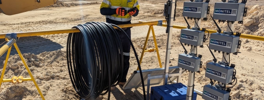
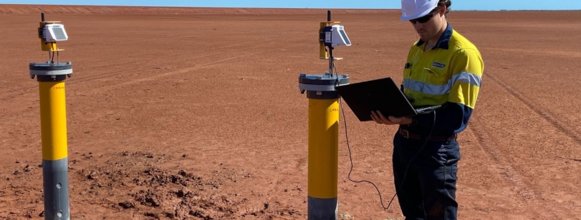
When installing a piezometer, engineers want to set it up for long-term performance, stability and safety. A critical (but often overlooked) step in that process is potting.

At Monitel, we pot our sensors with methods that are proven to hold up in Western Australia’s harshest conditions. Integrated into wider monitoring systems, our units support high-integrity data collection over vast periods of time.

In this article, we explain what piezometer potting is, why it’s essential in geotechnical installations and how we tailor our processes to meet the demands of site conditions and regulatory requirements.

What Is a Piezometer?

A piezometer is a sensor used to measure pore water pressure within soil, rock or other geological materials.

Piezometers are commonly installed in boreholes, tailings dams and excavation sites to track long-term changes pressure. Their data can be critical in understanding subsurface stability and geotechnical risk. That might include slope failures, foundation movement or structural instability.

Monitel supplies and installs a range of piezometer types suited to different applications, including vibrating wire, standpipe, strain gauge and pressure transducer models.

What is Potting?

In the context of piezometers, potting refers to the process of sealing the electrical connection point between the sensor and its signal cable. This is typically done using a resin compound designed to:

  • Protect against water ingress
  • Secure the internal wiring
  • Provide mechanical strain relief
  • Prevent sensor failures caused by corrosion or movement

Potting keeps the sensitive interface between sensor and cable fully sealed from the elements. That’s what secures accurate readings in long-term and deep installations.

Why Does Potting Matter?

1. Waterproofing and Moisture Protection

Even the smallest gap at the cable junction can allow moisture into the sensor body, corrupting readings and causing signal failure. This is especially true for a vibrating wire piezometer, which relies on signal consistency to monitor subtle changes over long periods.

Our team use potting compounds rated for high humidity and full submersion, essential for protecting installations in saturated boreholes, tailings dams or groundwater monitoring wells.

2. Strain and Vibration Resistance

In remote or geotechnically active environments, piezometers must withstand movement, vibration and cable tensions. Potting prevents any of these being transferred to the sensor connection, reducing the risk of long-term fatigue and detachment.

If your site is experiencing heavy vehicle traffic, blast vibration or ongoing settlement, these benefits are particularly important to your sensors’ lifespans.

3. Chemical and Thermal Durability

Whether they’re home to mining, landfill or infrastructure projects, many WA sites endure aggressive chemical and temperature conditions. At Monitel, we select potting compounds that resist chemical degradation and fluctuations caused by high temperatures.

How Monitel Implements Best Practices in Potting

At Monitel, we don’t treat potting as an afterthought. It’s built into our wider installation process and includes:

  • In-field potting stations that allow us to immediately seal sensors during deployment.
  • Sensor-specific materials are matched to the piezometer type and site conditions. That ensures your whole system is self-integrated.
  • Documented quality assurance with photographic records and batch numbers for potting compounds used.
  • Cable protection sleeves and seals are installed alongside the potted area for extra redundancy.

In deeper boreholes, we may opt to factory-pot sensors prior to mobilisation to avoid issues and retrieval and replacement.

What Potting Material Should You Use?

Different types of potting materials come with different durabilities, signal stabilities and long-term accuraces. At the same time, different piezometers, installation depths and site conditions demand tailored compounds that balance sensor protection with signal transmission.

For vibrating wire piezometers, epoxy-based compounds are often used because of their excellent adhesion and resistance to water ingress. These materials form a rigid seal around the cable and strain-sensitive components, ensuring stability during ground and temperature changes.

On the other hand, managers might select a urethane or silicone-based compound for its flexibility where movement or vibration is a concern.

Supporting Reliable Monitoring in WA Conditions

It doesn’t matter what you’re monitoring – the integrity of your piezometer data depends on every detail. That includes how the sensors are potted.

Working with Monitel, you gain a partner that understands how field conditions impact long-term performance. We deliver robust, potted sensors that are fit for your regulatory, engineering and operational needs.

We can assist with installation for a:

  • Vibrating Wire Piezometer
  • Standpipe Piezometer
  • Drive Point Piezometer
  • And other types of sensor

For more information or to enquire about potting services, contact Monitel.

Installing a vibrating wire piezometer in a deep borehole requires careful planning, reliable instrumentation and a comprehensive methodology. With proper preparation, you set your self up for high-quality data with long-term reliability.

In Western Australia, extreme ground conditions and strict regulatory expectations are the norm, so precision in borehole installations is essential for effective monitoring.

Drawing on Monitel’s practical experience in WA industry, this guide outlines best-practice techniques for vibrating wire piezometer installation in deep boreholes.

What Is a Piezometer?

A piezometer is a geotechnical instrument used to measure pore water pressure in soil, rock or fill material. The vibrating wire piezometer is a subcategory of this sensor that converts pressure changes into frequency shifts in a tensioned wire. Those are then translated into pressure readings.

They have a rugged design, long-term stability and are resistant to electrical noise – making them ideal for deep installations and remote monitoring. That might include tailings dam surveillance, groundwater management projects or a broader regulatory compliance system.

Planning for Deep Borehole Installations

Before installation, project managers and engineers must define:

  • Target monitoring depth(s)
  • Expected groundwater and geotechnical conditions
  • Borehole diameter and casing type
  • Backfill requirements
  • Data retrieval method

Our team can assist with site-specific assessments to determine the ideal installation plan. For deep boreholes, a vibrating wire piezometer is preferred for its signal integrity and compatibility with automation.

Step-by-Step Installation Method

1. Drill and Log the Borehole

Using the appropriate drilling technique, we advance the borehole to the required depth. Our team also collect data during this stage to verify stratigraphy and determine the placement of sensors.

2. Assemble the Sensor

Each vibrating wire piezometer is assembled with its cable, protective tubing and a porous filter tip. We ensure they are waterproofed and tested for signal integrity prior to deployment.

3. Position the Sensor at Depth

We lower the sensor to the target depth using a weighted guide or PVC pipe to prevent twisting and tangling. If multiple sensors are being installed in the same hole, we pre-plan a string with sensors at designated intervals.

4. Place Filter Sand

A graded silica sand is poured around the piezometer tip to ensure hydraulic connection with the surrounding soil or rock. It enhances the sensor’s ability to measure true pore pressure.

5. Seal the Zone

Our team isolate the measurement zone with a bentonite pellet or grout seal. This prevents vertical seepage and hydraulic short-circuiting, both of which distort readings.

6. Backfill the Borehole

The remainder of the borehole is filled with bentonite, cement grout or a mix of both. If multiple sensors are installed, we may alternate sand and bentonite seals.

7. Cable Protection and Surface Termination

Protected with conduit or casing, sensor cables are routed up the borehole. At the surface, they are terminated in the datalogger of your choosing. Our team will make sure all installations are secured and labelled for easy maintenance.

Considerations for Western Australian Conditions

In WA, deep boreholes are often located in remote, high-temperature and/or corrosive environments like:

  • Mine pit walls in the Pilbara
  • Tailings dams in Goldfields regions
  • Transport corridors over reactive clay formations

These conditions are harsh and unforgiving, so it’s important to select a VWP with an appropriate cable length, pressure range and temperature tolerance. We also stock and install high-temperature vibrating wire piezometers for sites where geothermal gradients or buried infrastructure make standard hardware unviable.

When it comes to data acquisition, we design systems with WA’s telemetry limitations in mind. That includes automated, solar-powered and satellite-capable options where cellular coverage is poor or regular access is difficult.

Choose Monitel for Vibrating Wire Piezometer Installations?

There’s no single solution to installing a vibrating wire piezometer in a deep borehole. For a seamless, precise installation you need to consult geotechnical specialists and invest in reliable instrumentation.

That’s exactly what we deliver across Western Australia. With a tailored monitoring system and hands-on support, Monitel can help you assess subsurface conditions with confidence.

From installation to data interpretation, we take a technology agnostic approach that prioritises the needs of your site. We don’t choose the sensors convenient to us – we choose the sensors ideal for you.

If you’d like help designing or installing a VWP monitoring system for your site, contact the Monitel team today.

In Western Australia’s complex resource and infrastructure industries, the piezometer has proven an essential tool for geotechnical and environmental monitoring.

Proper piezometer installation is crucial to obtaining reliable data, whether it’s for monitoring groundwater levels, pore water pressure or supporting regulatory compliance.

In this guide, we outline the general steps for installing common types of piezometer and some important considerations for ensuring long-term accuracy and performance.

What Is a Piezometer?

A piezometer is a sensor used to measure pore water pressure within soil, rock or fill material. They detect the pressure of groundwater in a specified zone, helping engineers assess ground stability, seepage risk and the effectiveness of drainage systems.

They are essential for borehole monitoring, tailings dam safety, and infrastructure development, where understanding subsurface behaviour is critical to structural integrity and regulatory compliance. Here’s how they should be installed:

Step 1: Planning the Installation

Before any fieldwork, you must undertake detailed planning. A well constructed plan includes:

  • Site assessment: Understand the geotechnical conditions.
  • Sensor selection: Choose the appropriate piezometer type (e.g. vibrating wire for long-term data, standpipe for manual monitoring or pressure transducer for real-time remote reporting).
  • Depth determination: Define your monitoring depths based on the zone of interest.
  • Compliance check: Ensure installation plans meet relevant WA regulations, such as Work Health and Safety (Mines) Regulations 2022, DWER licensing conditions and local government requirements.

Monitel supports clients in designing installation plans that produce high-quality data and are compliant with relevant guidelines

Step 2: Drilling or Driving the Borehole

Most piezometers are installed in boreholes, although some models can be deployed without drilling (such as drive-in).

For borehole installations:

  • Drill to the target depth using appropriate methods
  • Use temporary casing to prevent collapse during installation, especially in unconsolidated soils.

For drive-in piezometers:

  • Use a drop weight or pushing system to insert the sensor directly into soft soils. This will minimise site disturbance.

Be sure to make observations and log soil and groundwater data during drilling. This can prove useful when adjusting the final sensor placement.

Step 3: Sensor Placement

For vibrating wire and strain gauge piezometer installation:

  • Position the sensor tip at the specified depth.
  • Surround it with clean, saturated silica sand to ensure hydraulic connectivity.
  • Install a bentonite seal above the sand layer to isolate the sensor zone from upper groundwater.
  • Backfill the remaining borehole.

For standpipe piezometers:

  • Lower the open-ended PVC pipe (with porous tip) to the target depth.
  • Install sand around the tip, followed by a bentonite plug to isolate the intake zone.
  • Cap and protect the top of the pipe with a surface casing for easy manual readings.

For pressure transducer models:

  • These can be installed inside standpipes or directly in open boreholes.
  • Cable management and seal integrity are key to avoiding data noise and water ingress.

Step 4: Data Connection and Logging

Once the sensors are placed, connect cables to a logger or telemetry system. Monitel offer telemetry compatible systems for:

Data can be manually downloaded or sent to a cloud-based dashboard with real time visualisation and alerting. Logging fequency can vary from every few minutes to daily.

Step 5: Surface Completion and Protection

We like to consider these two facts when constructing a monitoring system:

  • Piezometers are an investment
  • Your site likely needs long-term results for compliance and planning.

For those reasons, it’s critical to protect the installation from environmental degradation. To do so, you can:

  • Use a concrete pad or bollards to protect boreholes in trafficable areas.
  • Label the piezometer location clearly with ID, depth and installation date.
  • For standpipes, install a lockable cap to prevent tampering and contamination.

Step 6: Calibration and Initial Readings

Once installed:

  • Take baseline readings to establish pre-monitoring pore pressure conditions.
  • Verify logger configuration and connectivity.
  • For vibrating wire sensors, ensure the frequency range is correct and stable.
  • Log any field notes, weather or site activities that might influence early readings.

Tips for Long-Term Performance

If your vibrating wire or other piezometer installation will be monitoring long-term, you can keep your results reliable and accurate with:

  • Moisture seals: Always check that seals are intact (especially for electrical sensors).
  • Cable routing: Secure cables to reduce risk of movement, pinching or wildlife interference.
  • Redundancy: Consider a second piezometer to provide backup data.
  • Maintenance: Schedule routine data checks and site inspections. This is almost a necessity in rural WA, where extreme heat and harsh conditions are common.

Get in Touch for Assistance with Piezometer Installation

The Monitel team provide end-to-end piezometer installation services for geotechnical projects across Western Australia.

We’re trainined to understand the state’s unique climate and regulatory landscape and to ensure each system functions as designed. Whether you’re monitoring tailings dams, boreholes or embankments, we’ll keep your data accurate, secure and actionable.

For help with a piezometer installation, get in touch with Monitel.

Western Australia’s natural environment presents a unique and complex set of monitoring challenges. Whether it be high temperatures in the Pilbara or corrosive groundwater around coastal sites, sensors endure harsh conditions to gather accurate long-term data. This is where the vibrating wire piezometer (VWP) stands out.

Used to monitor pore water pressure in soil and rock, VWPs are a staple in resources, civil construction and environmental projects across WA. Their durability, reliability and resilience to climate extremes make them one of the most trusted sensor types for long-term ground behaviour monitoring.

In this article, we explain why vibrating wire piezometers are so well-suited to WA’s conditions and how our team integrate them into effective, regulation-compliant monitoring systems.

What Is a Vibrating Wire Piezometer?

A vibrating wire piezometer measures pore water pressure using a small, tensioned wire housed in a sealed sensor body. As groundwater pressure changes, the sensor’s diaphragm deflects, altering the tension of the wire. The tension change shifts the wire’s natural frequency, which is then recorded and converted into a pressure reading.

VWPs are most commonly installed in boreholes, tailings dams, earth embankments and foundation zones. Their stability and noise resistance make them ideal for long-term and remote monitoring applications.

Why Vibrating Wire Piezometers Work Well in WA

1. Highly Durable in Extreme Heat

In WA’s northern regions, monitoring equipment must be robust. The Pilbara and Kimberly regularly experience summer temperatures exceeding 45°C and a good vibrating wire piezometer is built to handle those conditions. For even harsher environments, Monitel offers high-temperature VWPs that can reliably perform in temperatures up to 250°C. These are constructed with reinforced materials suited to buried infrastructure and deep tailings dams.

2. Stable and Noise-Resistant in Remote Areas

Many Western Australian sites are located far from power and network infrastructure. VWPs produce a frequency-based signal that is resistant to signal degradation over long cable runs and unaffected by electrical interference. In simpler terms, they are perfect for remote monitoring.

In addition, they are also compatible with automated loggers and telemetry systems, reducing your need for frequent site visits.

3. Minimal Drift for Long-Term Projects

From civil infrastructure builds to tailings storage facilities, any long term monitoring program requires reliable data. VWPs exhibit minimal sensor drift, meaning their readings remain reliable for extended periods of time without the need for recalibration. This can be vital in satisfying long-term compliance obligations under WA’s mining and environmental frameworks.

4. Flexible Installation Options

A vibrating wire piezometer can be installed in a wide range of geological settings, from hard rock to soft tailings. At Monitel, we’ve deployed them:

  • In boreholes for groundwater pressure monitoring
  • Embedded in tailings embankments for seepage and uplift detection
  • Beneath settlement zones at major construction sites

Because they can be grouted in place or installed in sand-packed zones, VWPs are compatible with various borehole designs and casing types.

Why Monitel Recommends VWPs

At Monitel, we stand firm in our technology-agnostic approach. We never base a decision on brand allegiance or supplier preference, instead choosing a sensor to suit the needs of your project.

Vibrating wire piezometers often form the backbone of our monitoring systems. Their resilience in the field, capacity for automation and proven performance in WA conditions make them a reliable choice for many clients. We stock a diverse range of VWPs, including:

  • W9 – for general-purpose pore pressure monitoring in boreholes
  • High-Temperature VWPs – for tailings dams and buried infrastructure
  • Compact VWPs – ideal for small-diameter boreholes or constrained installations

Click here to view the full range and learn more about each model.

Regulatory Relevance in WA

Vibrating wire piezometers play an important role in demonstrating compliance with multiple Western Australian regulations:

  • Work Health and Safety (Mines) Regulations 2022
  • Mines Safety and Inspection Regulations 1995
  • DWER License and Environmental Guidelines

Monitel’s VWPs support early detection of rising pore pressures, enabling prompt interventions and reducing the risk of structural failure or regulation breach.

Need Help Selecting the Right VWP? Contact Monitel Today

Whether you’re monitoring a single borehole or looking to implement a large-scale system, our team are here to assist. We’ll help you choose the right vibrating wire piezometer, complete the installation process and ensure your project meets WA’s regulatory requirements.

For more information, you can contact our team on (08) 6219 8284 or at admin@monitel.com.au.

The Vibrating Wire Piezometer (VWP) is a trusted tool for measuring pore water pressure in geotechnical environments. From boreholes and tailings dams to embankments, tunnels and settlement zones, these sensors are can detect early warning signs of instability and protect regulatory obligations.

At Monitel, we specialise in selecting and installing VWPs that suit the demands of your site and project scope. In this article, we’ll explore where VWPs can be used and why they’re one of the most reliable sensor types for long-term, real-world monitoring.

What Is a Vibrating Wire Piezometer?

A vibrating wire piezometer uses a tensioned wire to measure changes in pore water pressure. As groundwater pressure acts on the sensor’s diaphragm, it changes the wire’s vibration frequency. That signal is converted into a pressure reading that can be logged on-site or transmitted remotely.

The vibrating wire piezometer is favoured for it’s ease of installation, accuracy and long-term stability. Furthermore, it is resistance to electrical interference and other cable noise makes it ideal for use in Western Australia’s remote regions where manual access is often limited.

We stock a wide range of VWPs, including:

  • Standard vibrating wire piezometers
  • High-temperature VWPs
  • Compact VWPs for constrained boreholes

You can see our full range of VWPs here.

1. Boreholes

VWPs are frequently installed in boreholes to measure groundwater and pore pressure at various depths. Our installations are tailored to borehole design, with proper backfill and sealing techniques used to isolate the measurement zone.

Their data can be used to support:

  • Dewatering programs
  • Foundation stability assessments
  • Environmental baseline studies
  • Long-term construction impact analysis

At Monitel, our team will often pair a VWP with other borehole instruments like standpipes and inclinometers. This allows for a more detailed profile of subsurface conditions.

2. Tailings Dams

Pore pressure is a critical to a tailings dam’s stability. By embedding a VWP in embankments or placing one at depth, site managers can detect:

  • Uplift pressure
  • Seepage
  • Pore pressure increase during rainfall or deposition events
  • Potential liquefaction risks

WA regulations such as the Work Health and Safety (Mines) Regulations 2022 and Mines Safety and Inspection Regulations 1995 require dam walls and surrounding zones to be stable and properly monitored. VWPs are a commonly used tool in these frameworks and have proven vital in ensuring ongoing viability.

3. Settlement and Pre-Load Zones

Construction sites with soft soils often require preloading to consolidate ground before building. During this process a vibrating wire piezometer can be installed beneath the pre-load to track how pore pressure dissipates over time. Pore pressure is a useful indicator in these circumstances, giving managers a strong sense of when it’s safe to proceed with foundation work.

Monitel successful monitored a pre-load zone at the Alkimos Desalination Plant, using a vibrating wire piezometer to track pore pressure beneath a proposed tank. The data assisted engineers in confirming soil stability, preventing premature construction and potential ground moment.

4. Tunnels and Underground Infrastructure

In underground projects, VWPs assist with:

  • Monitoring pore pressure changes near tunnel linings
  • Detecting ingress risks
  • Supporting dewatering programs during excavation

VWP data can help engineers understand water movement and identify pressure zones that threaten tunnel stability. In urban tunnelling projects, this monitoring also supports risk management for adjacent structures.

5. Landfill, Dams and Water Infrastructure

Beyond resources, environmental projects and civil construction, vibrating wire piezometers are used in:

  • Landfills, to track leachate movement
  • Water supply dams, to monitor seepage and pressure differentials
  • Desalination plants, for settlement and ground saturation assessments

Monitel’s systems can be tailored to suit different methods of data telemetry, allowing us to support different kinds of projects with various reporting obligations and site accessibility.

Contact Monitel & Learn More About How You Can Use a Vibrating Wire Piezometer

If you’re planning a project that involves groundwater, soft soils or slope stability concerns, constructing a robust and reliable monitoring system should be a key priority. Robust and accurate, it’s likely a VWP will be a part of that system.

At Monitel, we pride ourselves on being product-agnostic. From design through to decommission, you can trust that the VWP on your site is suited to your budget and needs.

If you would like to discuss vibrating wire piezometer applications, installation or pricing, you can speak with a member of our team at admin@monitel.com.au or on (08) 6219 8284.

A piezometer is a key part of any geotechnical monitoring plan. However, it is important to select a sensor that can perform accurately and reliably in your site’s environment.

In Western Australia’s more extreme industrial and resources settings, high-temperature conditions can make standard sensors unreliable or prone to drift. That’s where the high-temperature vibrating wire piezometer (VWP) comes in. Purpose-built to withstand elevated temperatures, these sensors offer accurate pore pressure data even when exposed to heat from buried infrastructure, geothermal gradients or tailings storage facilities.

In this article, we explain when a high-temperature VWP is necessary and how Monitel incorporates them into our structural monitoring systems.

What Is a High-Temperature Vibrating Wire Piezometer?

A high-temperature VWP functions the same way as a standard vibrating wire piezometer, using a tensioned wire and diaphragm to measure changes in pore water pressure. Where they differ is in their construction.

High-temperature VWPs are manufactured with heat-resistant materials and reinforced internal components, allowing them to perform reliably and accurately in temperatures up to 250°C. These sensors also maintain signal integrity under thermal stress, making them suitable for long-term, automated monitoring in locations where conditions would compromise other sensor types.

When Are High-Temperature VWPs Needed?

In projects where ground or fluid temperatures exceed the standard operating ranges of standard piezometers, a high-temperature sensor is essential. Common applications include:

1. Tailings Dam Facilities

Tailings dams can experience elevated temperatures due to chemical reactions, solar exposure or underlying geological conditions. Elevated pore pressure and heat can combine to reduce stability, increasing the risk of dam wall deformation or failure. High-temp VWPs offer accurate pore pressure data in these critical zones, helping operators meet the requirements of the Mines Safety and Inspection Regulations 1995 and WHS (Mines) Regulations 2022.

2. Buried Industrial Infrastructure

In WA’s energy and water sectors, buried pipelines and tanks may generate or retain heat, particularly in remote, arid regions. Monitoring the soil conditions surrounding these structures often requires sensors that can withstand the high ambient and subsurface temperatures common in WA’s regions.

3. Geothermal Projects and Deep Boreholes

Projects tapping into geothermal heat or those with deep borehole infrastructure may encounter naturally high temperatures. Opting for a high-temperature VWP will ensure that pore pressure measurements remain reliable, even when installed hundreds of metres below ground.

4. Preload Zones with Accelerated Settlement

When preload or surcharge strategies are used in hot conditions (for example, on shadeless industrial sites), standard piezometers may degrade over time. High-temp VWPs offer a resilience against these elements, assisting projects affected by vertical loading and thermal influence.

Benefits of High-Temperature VWPs

  • Thermal resilience: Maintains accuracy in elevated temperature zones.
  • Long-term stability: Suitable for continuous monitoring across months or years.
  • Signal integrity: Resistant to noise or degradation caused by heat and moisture.
  • Remote compatibility: Easily integrated with wireless loggers and telemetry systems.

Ambient and subsurface heat is a primary concern for many Western Australian projects. Robust and capable of high performance in extreme conditions, this sensor class can be the difference between early detection and unexpected failure.

How Monitel Implements High-Temp VWPs

At Monitel, our planning and investigation process includes an assessment of site-specific thermal risks. Where needed, we will complete the installation of a high temperature vibrating wire piezometer as part of a broader geotechnical monitoring plan.

Our team handles design, installation, telemetry integration and ongoing data interpretation to ensure your sensor selection aligns with site conditions and regulatory obligations.

High-temperature VWPs often form part of our:

  • Tailings dam monitoring systems
  • Borehole instrumentation programs
  • Settlement tracking and pre-load assessment tools

Monitel primarily deploys the VWPHT-3600, which boasts a pressure range up to 34.5 MPa and 3K and 10K thermistor options.

However, we pride ourselves on being brand and product agnostic, meaning we will always opt for the sensor best suited to your project and budget. We will never prioritise any brand allegiance.

Speak With Monitel About Sensor Selection

If you are unsure whether your project needs a high-temperature or standard vibrating wire piezometer, we’re here to help. Monitel works closely with geotechnical engineers and project managers to design and implement compliant, efficient monitoring solutions across WA.

For more information about vibrating wire piezometer installation, pricing and data, you can contact us at admin@monitel.com.au or call (08) 6219 8284 to speak with our team.

The vibrating wire piezometer (VWP) is known for its durability, accuracy and reliability in long-term geotechnical monitoring. But even the most robust of these sensors can run into problems if not installed, configured and maintained correctly.

Understanding the most common VWP errors (and how to fix them) is essential in keeping your monitoring system accurate and compliant with Western Australian regulations.

In this post, we cover typical issues encountered with VWPs across boreholes, tailings dams and settlement monitoring programs. You’ll also learn how Monitel helps clients prevent and resolve these errors in the field.

What Is a Vibrating Wire Piezometer?

A vibrating wire piezometer measures pore water pressure by detecting changes in the tension of its main wire. As pressure on the diaphragm changes, the frequency of the vibrating wire shifts. The frequency is then converted into readable data either manually or via automated loggers.

VWPs are known for their resistance to electrical interference and moisture, making them ideal for the challenging conditions so common across WA. However, their performance still depends on proper installation, configuration and calibration.

Common VWP Issues and How to Fix Them

1. No Signal or Flatline Readings

What’s the issue?: The sensor is not outputting any data or the signal is stuck at a constant value.

Possible Causes:

  • Broken or damaged cabling
  • Incorrect wiring to the data logger
  • Moisture ingress into the cable or junction box
  • A failed sensor (although this is unlikely)

How to Fix It:

  • Inspect all cabling and connectors for damage or water ingress.
  • Test the continuity of the cable using a multimeter.
  • Ensure that polarity and signal wiring are correctly configured at the logger.
  • If everything checks out but the sensor remains unresponsive, replacement may be necessary.

2. Unstable or Noisy Readings

What’s the issue?: The data shows irregular spikes, oscillations or inconsistent values.

Possible Causes:

  • Electrical noise interference (possibly from nearby equipment)
  • Poor grounding of the logging system
  • Loose connections or compromised shielding
  • Temperature fluctuations affecting unshielded installations

How to Fix It:

  • Relocate the sensor cable, creating distance from power sources or high-voltage equipment.
  • Check that the logger and all sensor cabling are properly grounded.
  • Use shielded cables and ensure connections are tight.
  • Consider using temperature compensation in the logger settings.

3. Drift Over Time

What’s the issue?: The sensor data gradually changes in one direction without any real change in pore pressure.

Possible Causes:

  • Sensor diaphragm degradation
  • Excessive temperature exposure (especially above rated range)
  • Air entrapment around the diaphragm
  • Long-term material fatigue

How to Fix It:

  • Use high-temperature VWPs such as the VWPHT-3600 for thermally active sites.
  • During installation, ensure full saturation of the filter tip to avoid air pockets.
  • If drift persists, recalibration or sensor replacement may be necessary.

4. Zero Readings in a Wet Environment

What’s the issue?: The piezometer is reading no pressure despite being submerged.

Possible Causes:

  • Incorrect elevation reference used during installation
  • The filter tip may not be fully saturated
  • Sensor was installed above the water table or pressure zone
  • Faulty logger calibration

How to Fix It:

  • Double-check piezometer depth against borehole logs or groundwater level data.
  • Ensure proper installation of sand and bentonite seals around the filter tip.
  • Validate and adjust logger calibration or reference values.

Preventing Errors During Vibrating Wire Piezometer Installation

With proper planning and execution, projects can avoid many of the problems listed above. At Monitel, we follow a strict vibrating wire piezometer installation process that ensures:

  • Sensors are selected based on site conditions (e.g. high-temp VWPs for heated environments)
  • Cabling and junction boxes are sealed and weatherproof
  • Boreholes are prepared with the correct sand filter and bentonite seal configuration
  • All sensors are tested and zeroed prior to installation
  • Data loggers are configured with project-specific tolerances and alert thresholds

We have designed this approach to keep all monitoring systems compliant with the the Work Health and Safety (Mines) Regulations 2022 and Mines Safety and Inspection Regulations 1995.

Effective monitoring and proven compliance are our priority. That is why we champion a product and technology agnostic approach, always choosing the best sensor for your site, not our bottom line.

Design and Implement a Monitoring System with the Monitel Team

Whether you’re installing VWPs for the first time or troubleshooting an existing system, the Monitel offers practical support. That includes:

  • Diagnostic testing for sensor and logger faults
  • Field recalibration and replacement services
  • Automated alert configuration and data reporting
  • System audits to ensure compliance with local requirements

If you would like to speak with our team about unusual data, absent data or another issue, please contact Monitel at admin@monitel.com.au or call (08) 6219 8284. Our team can help identify the cause and get your monitoring system back on track.

To ensure stability, structural integrity and compliance on site, project managers must have a firm understanding of pore pressure behaviours. For complex sites like tailings dams and deep boreholes, a vibrating wire piezometer (VWP) can prove an important tool.

Known for their high accuracy and reliability in long-term monitoring, VWPs provide the data that allows engineers to make informed, proactive decisions. But what exactly should you be watching for when analysing VWP data?

This article outlines the key pore pressure trends to monitor, what they mean for your project, and how Monitel can support you in interpreting and acting on these changes.

If you would like to learn more about vibrating wire piezometer selection, installation and pricing, please contact our team.

What Is Pore Pressure and Why Does It Matter?

Pore pressure is the pressure exerted by water within the pores of soil or rock. It has a direct influence on ground stability, particularly under load or during changes in moisture, temperature or excavation. If allowed to rise beyond expected levels, pore pressure can slop failures, foundation instability or, in the case of tailings dams, collapse.

Continuous monitoring with a VWP is the surest way to identify warning signs early and implement proactive responses before conditions become unsafe and non-compliant.

What is a Vibrating Wire Piezometer and How Does it Capture Pore Pressure Trends?

Capable of high-performance in harsh environments, VWPs are the preferred sensor for much of WA’s resources and infrastructure industries.

They convert water pressure changes into frequency signals, which are logged either manually or via automated data acquisition systems. This makes them especially useful for establishing baselines and monitoring fluctuations over time. VWPs can be installed in boreholes, embankments and dam walls, amongst other applications.

The 5 Pore Pressure Trends You Should Monitor

1. Seasonal Variation

In surface soils and shallow boreholes, you’ll often see pore pressure fluctuate with seasonal rainfall and evaporation cycles. Sites must ensure that any changes in data match climate variations. For example, higher readings after prolonged wet periods are normal, but sudden increases outside expected rainfall windows may indicate water ingress or drainage failure.

What to watch for:

  • Gradual pressure rise during rainy seasons
  • Return to baseline during dry conditions
  • Anomalous surges outside seasonal norms

2. Construction-Induced Changes

On active sites like road, tunnel or mine developments, pore pressure may change in response to ongoing works. This could be the cause excavation, dewatering or loading. A spike may reflect stress redistribution or soil saturation and more rapid changes should be afforded immediate attention.

What to watch for:

  • Sudden jumps in pressure following excavation or fill
  • Unexpected recovery of pressure after dewatering
  • Persistent pressure elevation without external cause

3. Consolidation Trends

In soft clays, pore pressure will initially rise under new load before dissipating as water escapes and soil consolidates over time. A well-installed vibrating wire piezometer can help track this consolidation curve, indicating settlement rates and potential for future movement.

What to watch for:

  • Initial high readings after load placement
  • Steady decline in pressure as water drains
  • Deviations from expected settlement curves

4. Tailings Dam Pore Pressure Build-Up

Excess pore pressure within a tailings structure could indicate that material is not draining properly or that there’s seepage from upstream sources. When installed at various depths VWPs will pinpoint the layer or zone of concern.

What to watch for:

  • Pressure increase after new tailings deposition
  • Inconsistent readings between piezometer layers
  • Lack of expected dissipation over time

5. Groundwater Recharge and Drawdown

When monitoring wells, VWPs can track groundwater responses to nearby abstraction, rainfall events or aquifer recharge. These trends help model aquifer behaviour and support compliance with the Department of Water and Environmental Regulation (DWER).

What to watch for:

  • Slow recharge rates indicating reduced permeability
  • Rapid drawdown suggesting over-abstraction
  • Long-term baseline shifts across seasons or years

Contact Monitel for Reliable, Accurate & Informed Vibrating Wire Piezometer Data

Pore pressure is a dynamic, high-stakes factor on geotechnical sites. While VWPs provide the raw data, it takes contextual understanding to interpret it. This is where Monitel supports clients: by going beyond installation to create actionable monitoring frameworks.

Our team helps interpret vibrating wire piezometer data by:

  • Establishing site-specific baseline pressure levels
  • Creating trend thresholds for alerts
  • Automating data transmission and flagging anomalies
  • Linking pressure changes with onsite activities or environmental events

This ensures that pore pressure trends are not just recorded, but used to improve site safety respond early to prevent instability and delay.

At Monitel, our team have created tailored monitoring systems on sites across Western Australia. To learn more about how we can help you monitor pore pressure safely and effectively, contact us at admin@monitel.com.au or call (08) 6219 8284.

To ensure reliable data and long-term monitoring success, you must choose the right piezometer.

Two of the most commonly used sensors in this class are the Vibrating Wire Piezometer (VWP) and the Standpipe Piezometer. Each has distinct advantages and limitations, and choosing the right one depends on your site conditions, regulatory obligations, data needs and project duration.

In this article, we outline how the two compare and offer guidance on when to use each. For more information about vibrating wire piezometer installation, monitoring and costing, get in touch with our team.

What Is a Standpipe Piezometer?

A standpipe piezometer is a simple groundwater monitoring tool typically installed in a borehole. It is constructed with a porous filter tip connected to a riser pipe, which extends to the surface. The water level inside the pipe is a direct reflection of the pore water pressure at the depth of the tip.

These systems are most commonly used for manual monitoring, where water levels can be comfortably measured with a tape, float or pressure transducer.

Key features:

  • Cost-effective and easy to install
  • No power supply required
  • Suitable for short- to medium-term projects
  • Provides water level readings, not continuous pressure data

What Is a Vibrating Wire Piezometer?

A vibrating wire piezometer is an electronic sensor that measures pore pressure using a diaphragm and vibrating wire mechanism. Changes in pore pressure alter the tension in the wire, which is converted to a readable frequency signal and recorded by a logger.

VWPs are widely used in infrastructure, resources and tailings dam projects in WA. They are a particularly popular choice where automated, real-time monitoring is a requirement.

Key features:

  • High accuracy and stability
  • Suitable for long-term monitoring
  • Compatible with remote and automated systems
  • Performs well in harsh or saturated conditions

Key Comparisons

Feature Standpipe Piezometer Vibrating Wire Piezometer
Cost Low initial cost Higher upfront cost
Data Collection Manual, periodic Automated, continuous
Installation Simple borehole install Requires cabling and loggers
Accuracy Limited to water level High-resolution pressure readings
Suitable Environments Low-risk or temporary projects Complex, regulated, long-term sites
Use in Tailings Dams Rarely suitable Common and often required
Regulatory Suitability Basic compliance Supports detailed reporting for WHS & DWER

When to Use a Standpipe Piezometer

Standpipe piezometers are suitable for:

  • Environmental baseline studies with occasional data requirements
  • Short-duration construction sites that don’t need automated alerts
  • Sites where funding or access constraints prevent a more complex or automated system
  • Manual verification alongside automated systems

These applications reveal the standpipe piezometer’s 3 key advantages: simplicity, ease of installation and a minimal need for infrastructure.

On the other hand, they offer limited resolution and are not suitable for projects requiring real-time pressure updates.

When to Use a Vibrating Wire Piezometer

VWPs are preferred for:

  • Tailings dam monitoring, where accurate, continuous pressure tracking is often mandated by WA regulations
  • Borehole installations, particularly those supporting settlement studies, embankment behaviour or water table monitoring
  • Infrastructure and mining compliance, where the Mines Safety and Inspection Regulations 1995 and WHS (Mines) Regulations 2022 require robust data
  • Automated early warning systems, particularly in areas of known instability

Standard VWPs boast a robust build, but there are also high-temperature models available. These are a suitable choice for monitoring in remote WA, where harsh conditions are often a barrier for accurate and reliable data. Furthermore, most VWPs can be set up with automated telemetry, reduing the need for site visits.

Which Sensor Is Right for You?

If you are looking to construct a monitoring system, ask the following when choosing between VWPs and standpipes:

  • What are the regulatory requirements for my project?
  • Do I need real-time or high-frequency data?
  • How long will the monitoring period last?
  • Is remote or automated access important?
  • What is the risk level if pore pressure is not closely tracked?

For low-risk or temporary sites, standpipes may be sufficient. But for regulated, high-stakes or long-term projects, VWPs are the safer, more informative choice.

Contact Monitel for Structural and Geotechnical Monitoring Advice

Choosing the right piezometer is about ensuring your data is reliable, actionable and suited to your project’s requirements. In Western Australia, where regulatory frameworks and geotechnical conditions are demanding, Vibrating Wire Piezometers are increasingly becoming the standard.

At Monitel, we offer vibrating wire, standpipe and other varieties of piezometer. Guided by our product agnostic approach, our team will advise you on the system best suited to your site and budget. Following design and selection, you can rest easy knowing that we will continue to support you through installation, data collection and compliance reporting.

To speak with us about your monitoring needs, contact Monitel at admin@monitel.com.au or call (08) 6219 8284.